◎欢迎参与讨论,请在这里发表您的看法、交流您的观点。
1. Introduction
The pipeline booster pump is a horizontal pump, single-stage double-suction, high-flow, high-speed chemical pump, API610 standard BB1 pump. Most of the pumps on the market today use four or six speeds. Low-speed pumps are difficult to design, but the pump head size is large and the manufacturing cost is high. Due to the extremely strict requirements on pump efficiency, it is necessary to meet the national standard A line standard, making the hydraulic design of the pump a difficult point.
Today, CFD technology has been widely used in the prediction of pump performance, the design and optimization of hydraulic components. Based on the numerical simulation technology and the mature experience of the design and manufacture of the double-suction pump of the large pump-resistant industry, this paper designs and optimizes the hydraulic design of a certain type of pipeline booster pump. It has been verified by experiments that the comprehensive performance has reached the international leading level.
2. The impeller design and performance prediction
Design parameters are as follows
Flow Q: 3600 m3/h Head H: 230 m Speed r: 2990 rpm Required NPSH NPSHr: 35m
Impeller design
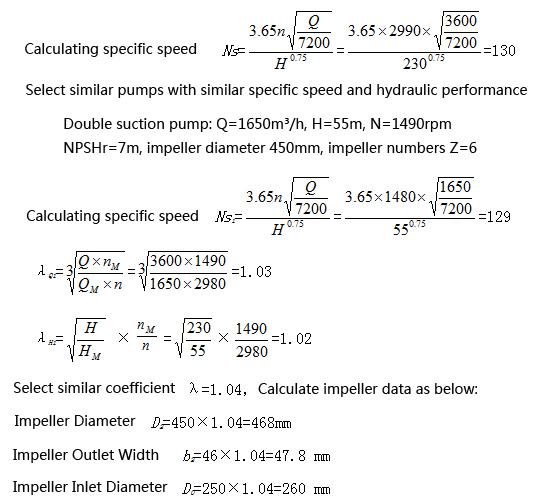
Calculate the specific speed, and compare the existing mature and efficient hydraulic model, decided to design the impeller by similar conversion method.
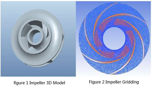
The three-dimensional modeling of the impeller obtained by similar conversion is shown in Fig. 1. Then use the grid generation software ICEM to mesh the impeller 3D model, as shown in Figure 2. The impeller uses a non-structural tetrahedral mesh to mesh the locations where the flow parameters of the blade face, back and blade inlets change dramatically. Automatically generate meshes, modify the mesh automatically or manually, so that the overall quality of the mesh reaches 0.4 or more, and the final mesh number is 602681. Introduce the grid into the CFX-pre software, set the impeller inlet surface property to the inlet flow velocity v=13.7m/s, the impeller outlet surface property to open, the rotation speed n=2980rpm, and simulate the impeller separately using the standard k-ε turbulence model. Convergence within 100 steps.
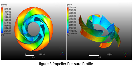
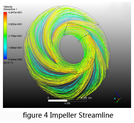
The calculation data was imported into the CFX-post software for analysis. Observe the pressure distribution of the blade and the front and rear cover plates, and the impeller flow line, as shown in Figures 3 and 4. It can be determined that the overall performance of the impeller is good, the pressure is evenly changed, and the streamline is stable without vortex. Using the Liquid Pump Performance module in the CFX-POST software, the impeller efficiency is 96.9%. Since the impeller is simulated separately, only the flow field and pressure distribution are observed, and the obtained outward characteristics of the lift are not accurate and are ignored here.
3. Pump body hydraulic design and performance prediction
3.1. Pressing room design
Base circle diameter D3
The reference model pump body hydraulic model is similarly converted and selected by structural parameters
The base circle D3 = 1.1 × D2 = 1.1 × 470 = 517 mm, and rounded to take 520 mm.
Pressurized chamber inlet width
After similar conversion, take the cross-sectional width of the vortex chamber b3=146mm
Calculation of the cross-sectional area of the vortex chamber
Because the pump body needs to be equipped with four types of rotors of 0.5 Q, 0.7 Q, Q, and 1.25 Q, the area of the throat section is appropriately enlarged on the basis of similar conversion to meet the performance requirements of the large flow rotor. According to D3, b3 and the cross-sectional area, the radial dimensions of each section can be calculated.
Starting from the initial section, take a section every 45° to ensure a uniform change in the cross-sectional area of the volute. The initial hydraulic design of the pump body is over.
3.2. Prediction of hydraulic performance of pump body
In order to verify the hydraulic performance of the pump body, the pump body components are three-dimensionally shaped. The designed impeller and the pump body components are combined and output in *.stp format, and imported into the ICEM software for mesh division, as shown in Fig. 5. The fluid area of the inlet and outlet pipelines adopts a structured grid. The impeller, the volute and the semi-spiral suction chamber adopt a non-structural tetrahedral mesh, and the volute tongue is encrypted. The grid is manually modified to achieve the overall quality of the grid. 0.4 or more. The overall mesh number is 2486227, of which the outlet section is 98400, the impeller 563092, the inlet section 141825, the volute 917451, and the suction chamber 417790.
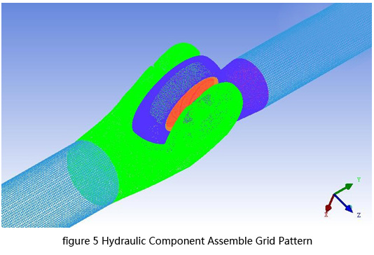
The grid is imported into CFX-pre software, using the standard k-ε turbulence model. The inlet boundary is set to the inlet speed according to the flow rate, the outlet boundary is set to open, and the target pressure is set to 23 atm. An interface is provided between each two adjacent model bodies. The interface models between the non-rotating body and the non-rotating body are set to general connection, the frame change model is set to none, and the interface models between the non-rotating body and the rotating body are set to general connection. The frame change model is set to frozen rotor. The model is simulated at six flow points of 0.6Q, 0.8Q 0.9Q, 1.0Q, 1.1Q, and 1.2Q. Calculate the 2000 step. Although the calculation does not converge but the inlet and outlet pressure is stable for a long time, the calculated data can be used.
The calculation data was imported into the CFX-post software for analysis. The external characteristic parameters were obtained using the Liquid pump performance module. The results were lower than the design requirements, and the pressure distribution and flow lines in the volute were analyzed, as shown in Fig. 6.
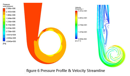
The fluid creates a large vortex at the diffuser, and the pressure distribution does not change uniformly from the VI section. That is to say, the hydraulic design of the volute has defects, resulting in a large amount of energy loss, which is the direct cause of the low efficiency of the hydraulic design.
4.The pump body hydraulic optimization and prediction
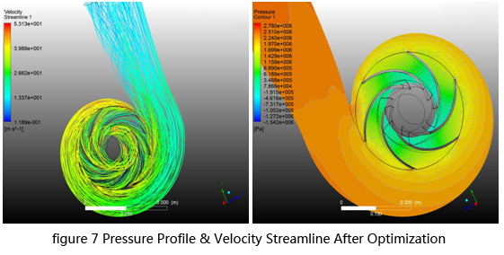
Based on the analysis of the convection field, it is decided to change the cross-sectional area after the IV section of the volute and increase the helix angle of the tongue to improve the energy recovery efficiency. After redesigning the volute, the new method is simulated by the same method. The optimized volute pressure distribution and streamline are shown in Fig. 7.
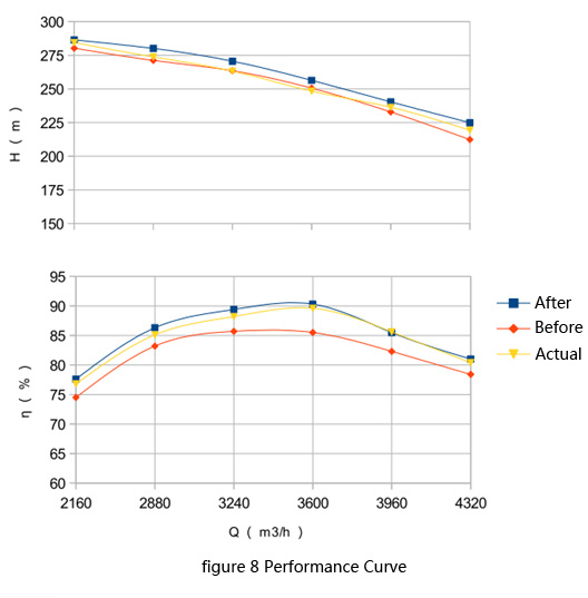
The pressure distribution of the volute is obviously uniform, and there is no obvious vortex. It can be seen that energy is efficiently converted from velocity energy to pressure energy, and the efficiency is improved. The external characteristic parameters are compared with those before optimization, as shown in Fig. 8. The optimization solution has reached the design requirements.
5. Performance test and comparative analysis
After the trial production and test of the full-scale prototype, the comparison between the measured results and the theoretical calculations is as follows:
◎欢迎参与讨论,请在这里发表您的看法、交流您的观点。