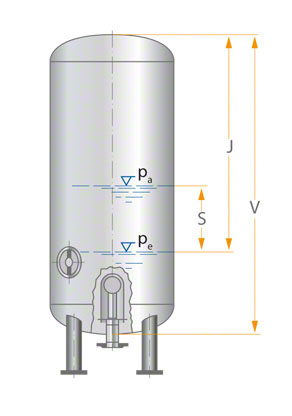
Accumulators for automatic pressure control in water supply systems (see booster systems) are usually installed vertically; few are installed horizontally. See Figure 1 Accumulator
The size of the accumulator depends on the number of starts (Z) of the pump set per hour. The number of startups depends on many factors. Information about the starting frequency should be obtained from the motor supplier (see starting frequency).
At the starting pressure (pe), the selected minimum water level must ensure that air cannot enter the discharge line under any circumstances. Therefore, the volume (V) of the accumulator should be selected to be 25% to 40% larger than the required effective accumulator volume (J). A compressed air shut-off valve can be provided as an additional component. The purpose is to prevent compressed air from entering the discharge line. If piping arrangements (such as domestic water supply systems) and horizontal vessels are unfavorable, the water level must be checked. If necessary, the connection must be placed in a lower position (eg dome).
The safety margin of 25% in the formula given below is used for battery selection.
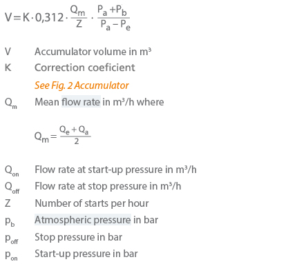
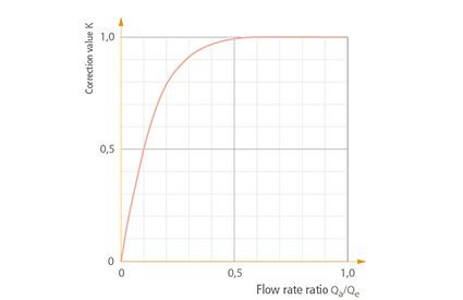
The proportion of available water (S) to the total volume (V) depends only on the starting pressure and the stopping pressure, which can be calculated by:
In an installation with multiple identical pumps, the size of the accumulator can be reduced by periodically switching between pumps to increase the number of starts and stops. Membrane accumulators are usually used in smaller units. These eliminate the need for compressed air shut-off valves or compressors. In this case, in addition to the effective volume (J), no additional volume of 25% to 40% is required.
The number of pumps in the booster system is independent of the calculation of the accumulator volume. If multiple pumps with different flow rates are used, the maximum pump average flow rate should be used in the formula. For systems in which multiple pumps perform flow control and only the base load pump starts and stops based on pressure, the accumulator size should be calculated based on the base load pump.
If such a smaller container can be accommodated in the available space more easily, the calculated accumulator volume needs to be subdivided among multiple accumulators, thereby reducing system cost. When distributing the volume between the two accumulators, the pressure settings for starting and stopping the pump can be set in such a way that the second accumulator is only filled with air.
If the volume is distributed to more than two accumulators, these accumulators must be connected through the gas (air) side to ensure that each accumulator is used evenly. See Figure 3 Accumulator
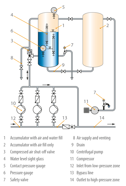
Since a certain percentage of the air in the accumulator is gradually absorbed by the pressure, the compressed air in the container must usually be replenished from time to time by the compressor. The size of the compressor depends on its suction capacity (Qk). The choice of compressor depends on the time (T) required to fill the entire accumulator volume. It is assumed that only two-thirds of the accumulator volume (equivalent to the water level at the stop pressure) must be filled with compressed air. The filling time should not exceed eight hours.
The suction (m3 / h) is:
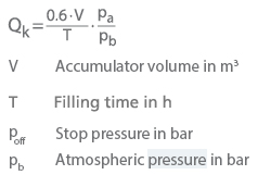
The working pressure of the compressor should at least correspond to the maximum stop pressure of the pump. The safety valve on the compressor must be preset to ensure that the maximum allowable working pressure of the accumulator is not exceeded.
According to the accident prevention regulations for pressure vessels (German Professional Association for Gas and Water Plants, Düsseldorf), it is not mandatory to install a safety valve on the accumulator of the centrifugal pump, as long as the H / Q curve of the pump (see characteristics Curve) may not exceed 1.1 times the maximum allowable working pressure of the container, and take measures to prevent the pump from severely overspeeding.
Accumulators are welded, cast, riveted, and occasionally trimmed in a strip-wound structure (used for very high pressures and temperatures in the chemical industry). The materials used are steel plates (boiler plates), non-ferrous metal plates, cast steel and plastics. The design and operation data of commonly used accumulators have been standardized.
